The Ultimate Guide to ATE Load Board Selection 2026: From Pin Count to Reliability
Quick Answer: What Defines a High-Quality ATE Load Board?
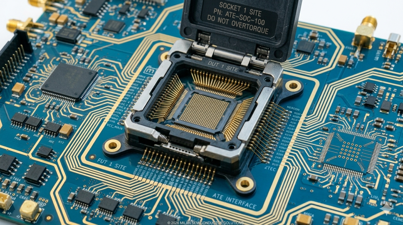
A high-quality ATE Load Board is the critical hardware interface connecting the tester (such as Teradyne UltraFLEX or Advantest V93000) to the Device Under Test (DUT). Its core value lies in precisely transmitting test signals and power, ensuring measurement accuracy and repeatability. An exceptional Load Board delivers low-loss signal transmission, stable power integrity, precise impedance control, and long-term reliability, ultimately enabling customers to achieve a higher First-Pass Yield while reducing system bring-up time.
Introduction
In semiconductor testing, the ATE Load Board serves as the “last centimeter” connecting the test system to the Device Under Test. No matter whether your tester is a Teradyne UltraFLEX or an Advantest V93000, a poorly designed Load Board will compromise even the most expensive test system’s ability to accurately evaluate chip performance.
This guide provides a comprehensive framework for Load Board selection, covering six critical dimensions: pin count and channel density, signal integrity, power integrity, thermal management, mechanical structure, and supplier evaluation.
1. Pin Count and Channel Density: Matching Tester to Device Requirements
The pin count of a Load Board determines both the number of devices that can be tested in parallel and the signal channels available per DUT.
Selection Guidelines:
| Device Type | Load Board Requirements |
|---|---|
| Low-pin-count devices (PMIC, discrete) | Standardized solutions acceptable; cost optimization priority |
| Medium-pin-count devices (MCU, mixed-signal) | Custom design required; focus on signal isolation and crosstalk control |
| High-pin-count devices (SoC, GPU, AI) | High-layer-count PCBs (≥80 layers), fine-pitch routing; deep platform expertise essential |
Platform-Specific Design Considerations
| Test Platform | Typical Applications | Load Board Design Requirements | Key Adaptations |
|---|---|---|---|
| Teradyne UltraFLEX, UltraFLEXplus | SoC, GPU, AI chips | High-speed differential signals, high pin count, complex power distribution | P-series instrument compatibility; high-speed signal eye diagram compliance |
| Teradyne J750 | MCU, mixed-signal | Medium pin count, cost-effective, high parallelism | 24-channel/card architecture; DIB layout optimization |
| Teradyne ETS364, ETS800, ETS88, ETS88TH | Analog, power devices | High voltage, high current, ultra-low noise | Power decoupling networks; Kelvin connection design |
| Advantest V93000 | SoC, RF, high-speed digital | High-frequency signals, precise impedance control | PS1600/PVIO adapter compatibility; S-parameter simulation |
| Advantest T2000 | Memory, SoC | High parallelism, high throughput | High-speed differential buses; thermal management |
2. Signal Integrity: Ensuring Test Data Accuracy
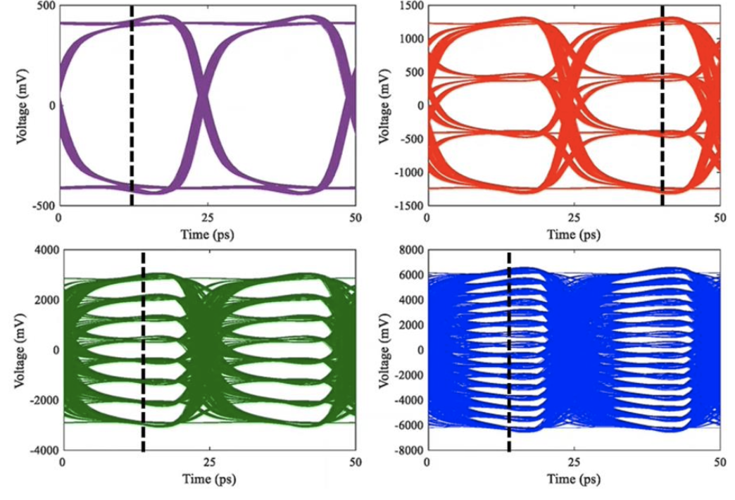
Signal integrity is the most critical technical challenge in Load Board design. In high-speed testing (>1Gbps), even minor impedance discontinuities can cause signal reflections and eye diagram closure, leading to test escapes or false failures.
Key Specifications and Design Requirements
| Parameter | Recommended Value | Design Considerations |
|---|---|---|
| Characteristic Impedance | 50Ω (single-ended), 100Ω (differential) | Maintain within ±5%; achieved through stack-up design and trace width calculation |
| Insertion Loss | -0.5 dB/inch @ 10GHz | Use low-loss materials (MEGTRON 6, Rogers 4000 series) |
| Return Loss | -20 dB @ 10GHz | Optimize via structures; minimize stubs; employ back-drilling; improved label PAD |
| Crosstalk | -40 dB @ 10GHz | Increase signal spacing; add ground isolation; use stripline structures |
| Eye Diagram Height | 90%UI | Validate through simulation; maintain design margin; optimize S parameter, harassment |
Practical Recommendation: When evaluating suppliers, require pre-layout and post-layout simulation reports and verify their capability to perform S-parameter testing using vector network analyzers.
3. Power Integrity: Delivering Clean Power to the Device
Modern chips demand exceptional power quality. AI chips, for example, may operate at core voltages as low as 0.8V while drawing transient currents exceeding thousands Amp, with voltage ripple requirements of less than ±3%.
Power Integrity Design Essentials:
- Low-Impedance Power Distribution Network: Achieve target impedance in the milliohm range through multi-layer power planes and optimized capacitor combinations.
- Decoupling Capacitor Placement: Follow the “large to small, far to near” principle; smallest capacitors (e.g., 100nF) should be placed closest to the DUT power pins.
- Kelvin Connections: For devices requiring precise voltage measurement (e.g., PMICs), implement 4-wire Kelvin connections to eliminate contact and trace resistance errors.
- Current-Carrying Capacity: Calculate required copper thickness and trace width based on maximum current; typically use ≥2oz copper, with heatsinks or fans for high-power applications.
4. Thermal Management: Addressing High-Power Device Cooling
With AI chip power consumption exceeding 500W, thermal management has become a critical design consideration for Load Boards.
Cooling Solution Options
| Cooling Method | Suitable Power Range | Design Considerations |
|---|---|---|
| Natural Convection | <10W | Increase copper area; incorporate thermal vias |
| Forced Air Cooling | 10–100W | Attach heatsinks; optimize airflow path |
| Liquid Cooling | >100W | Custom cold plates; sealed designs |
| Thermoelectric Cooling | Precision temperature control | Integrate TEC modules; closed-loop temperature control |
Reliability Requirements: For automotive devices, Load Boards must support tri-temperature testing (-40°C to 125°C). Material selection must account for coefficient of thermal expansion (CTE) matching to prevent solder joint cracking under thermal cycling.
5. Mechanical Structure: Stiffeners and Warpage Control
Large Load Boards (>400mm × 400mm) may experience warpage due to self-weight or temperature variations, potentially compromising probe contact reliability.
Mechanical Design Requirements:
- Stiffeners: Metal stiffeners mounted on the backside significantly enhance rigidity. Semiroc offers custom stiffener solutions optimized for board shape, weight, and mounting interfaces.
- Warpage Control: Industry standard requires warpage ≤0.1%. Achieved through symmetrical stack-up design, balanced copper distribution, and appropriate lamination processes.
- Mounting Interfaces: Ensure precise alignment of mounting holes and locating pins with the tester fixture.
6. Supplier Evaluation: From Capability to Service
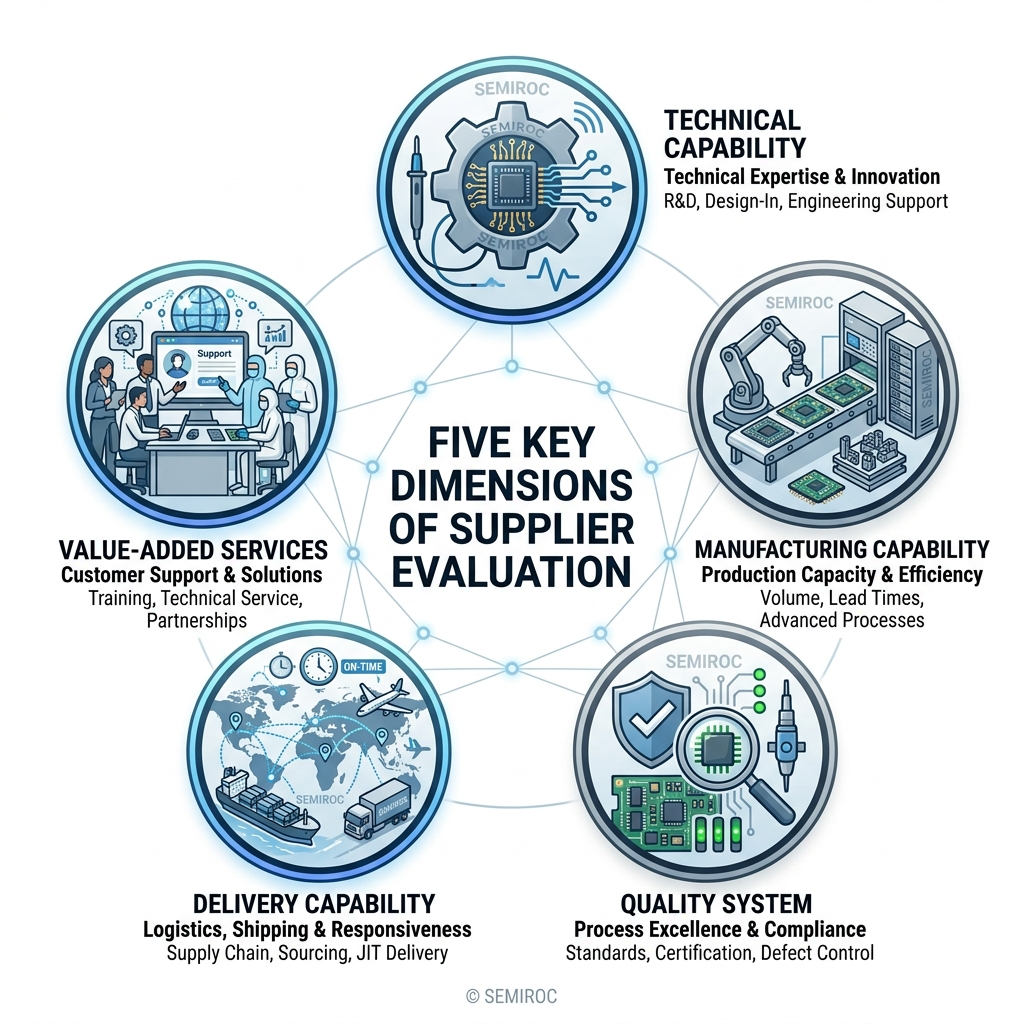
When selecting a Load Board supplier, evaluate the following dimensions:
| Evaluation Dimension | Key Assessment Criteria | Ideal State |
|---|---|---|
| Technical Capability | Simulation tools (SI/PI), design experience, platform expertise | Deep Teradyne/Advantest platform knowledge; proven high-speed/high-power design track record |
| Manufacturing Capability | PCB layer count, trace/space, material sourcing | ≥70 layers; 2 mil trace/space; established partnerships with Rogers and other material suppliers |
| Quality System | ISO9001, IATF16949, First-Pass Yield | FPY ≥85–95%; robust quality traceability system |
| Delivery Capability | Lead time commitments, emergency response | Standard lead time ≤3 weeks; expedite support for critical projects |
| Value-Added Services | Repair/refurbishment, health monitoring | Bin-1 ready service; online diagnostic tools |
Conclusion
The ATE Load Board may be small in size, but it carries immense responsibility in semiconductor testing. From pin count to signal integrity, from power delivery to mechanical structure, every detail influences final test yield and cost.
As a strategic partner of Teradyne, Semiroc has deep expertise in Load Boards, Probe Cards, and Cable Assemblies. We provide end-to-end Turnkey solutions—from simulation and design through manufacturing—enabling global customers to achieve 85–95% First-Pass Yield while reducing system bring-up time by 20–30%.
Contact our customer service team now to find answers to your questions.
CONTACT US